Image Gallery
(scroll to See More)
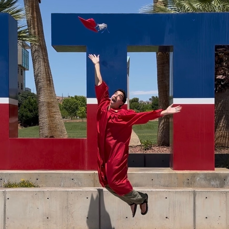
Me, jumping in the air with my grad cap.
Taken in 2026 after graduation at Utah Tech University by my lovely sister, Alanah.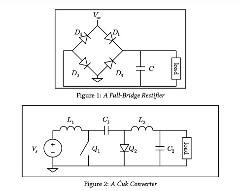
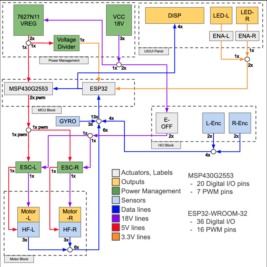
Circuits laid out with my Layout Library.
A full-bridge rectifier and Cuk converter circuit laid out with my typst circuit layout engine. The source for these figures is this:
    #figure(caption: [_A Full-Bridge Rectifier_],
        Circuit(
            Ground(Dir.SN),
            Diode("B002","GND",Dir.NWSE, label: $D_2$, flip: true),
            Diode("B002","B004", Dir.SWNE, label: $D_4$),
            Diode("B004","N001", Dir.NWSE, label: $D_1$),
            Diode("GND","B001", Dir.SWNE, label: $D_3$, flip: true),
            NetLabel("B004", Dir.SN, label: $V_"ac"$),
            Short("N001","N002", Dir.WE, size: 0.5),
            Capacitor("N002","N003", Dir.NS, label: $C$, flip: true),
            Short("N002","N004", Dir.WE),
            Impedance("N004",":N003", Dir.NS, label: rotate("load",90deg)),
            Short("B002","B00X", Dir.EW, size: 0.25),
            Wire("N003","B00X", flip: true),
        )
    )

    #figure(caption: [_A Cuk Converter_],
        Circuit(
            width: 11cm, height: 4cm,
            Ground(Dir.SN),
            VoltageSource("GND","N001",Dir.SN, label: $V_s$),
            Inductor("N001","N002",Dir.WE, label: $L_1$),
            Capacitor("N002","N003",Dir.WE, label: $C_1$, flip: true),
            Inductor("N003","N004",Dir.WE, label: $L_2$),
            Short("N004","N005",Dir.WE, size: 0.75),
            Switch("N002",":GND",Dir.NS, label: $Q_1$),
            Diode("N003",":GND",Dir.NS, label: $Q_2$),
            Capacitor("N004",":GND", Dir.NS, label: $C_2$, flip: true),
            Impedance("N005",":GND", Dir.NS, label: rotate("load",90deg)),
        )
    )
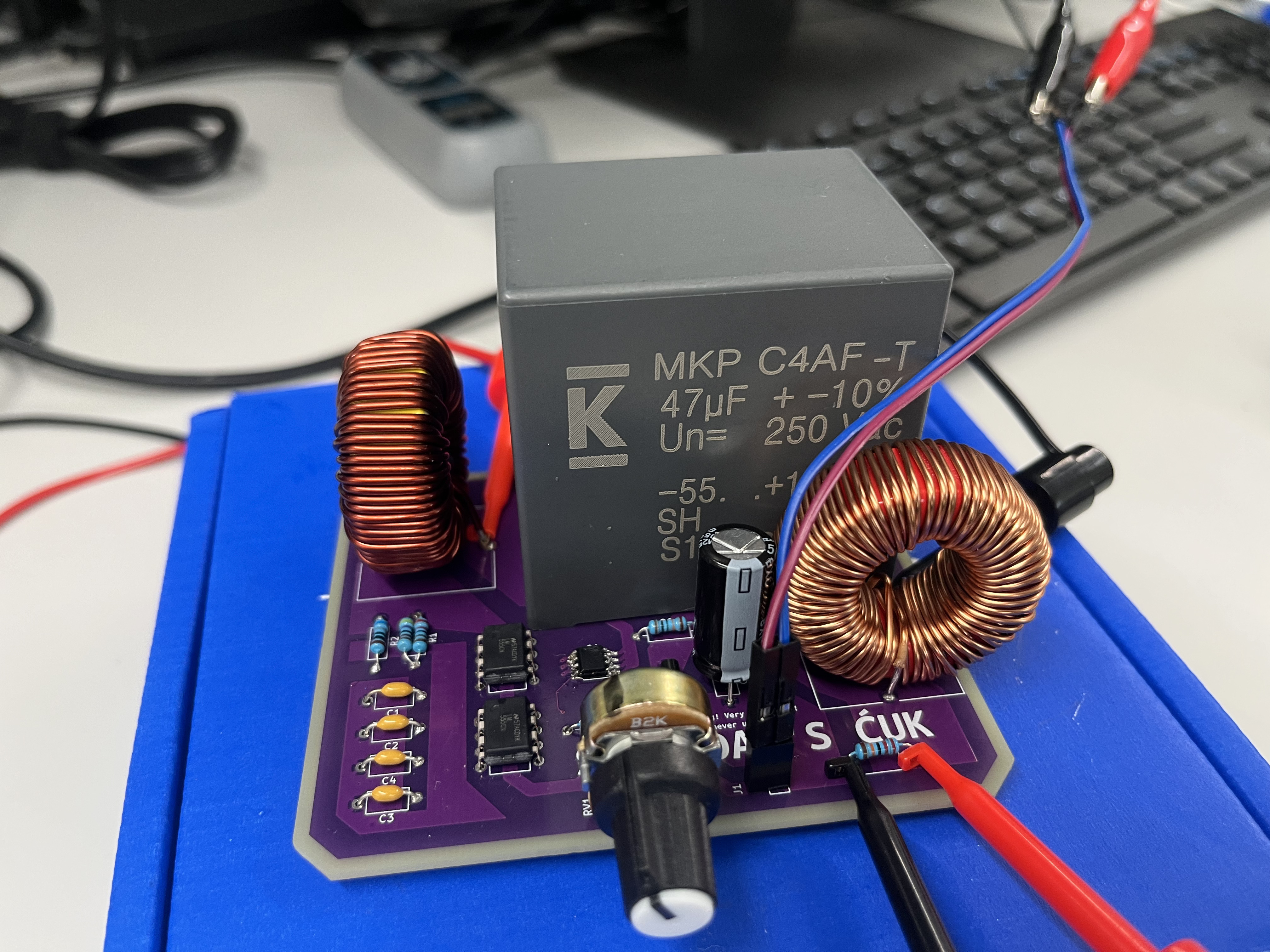
A fully-assembled Cuk converter.
Designed by myself and Stephen Harris, manufactured at JLCPCB.The Cuk Converter Slide Deck.
A Slide deck describing our Cuk Converter, its design, its goals, and its drawbacks. Contains screenshots of simulation data.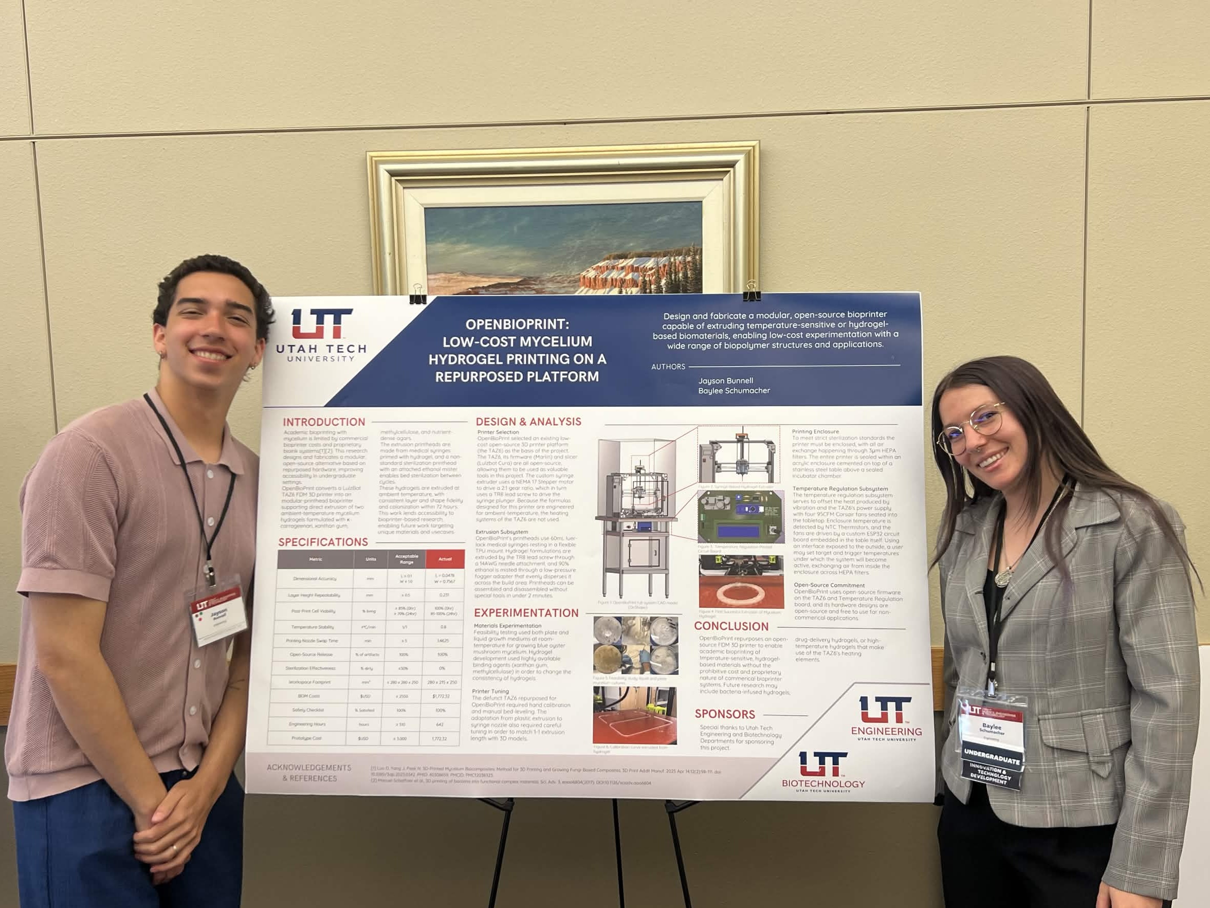
Me and Baylee Schumacher at Trailblazer Symposium.
Our first public presentation of OpenBioPrint, where we got to discuss our project with students and locals.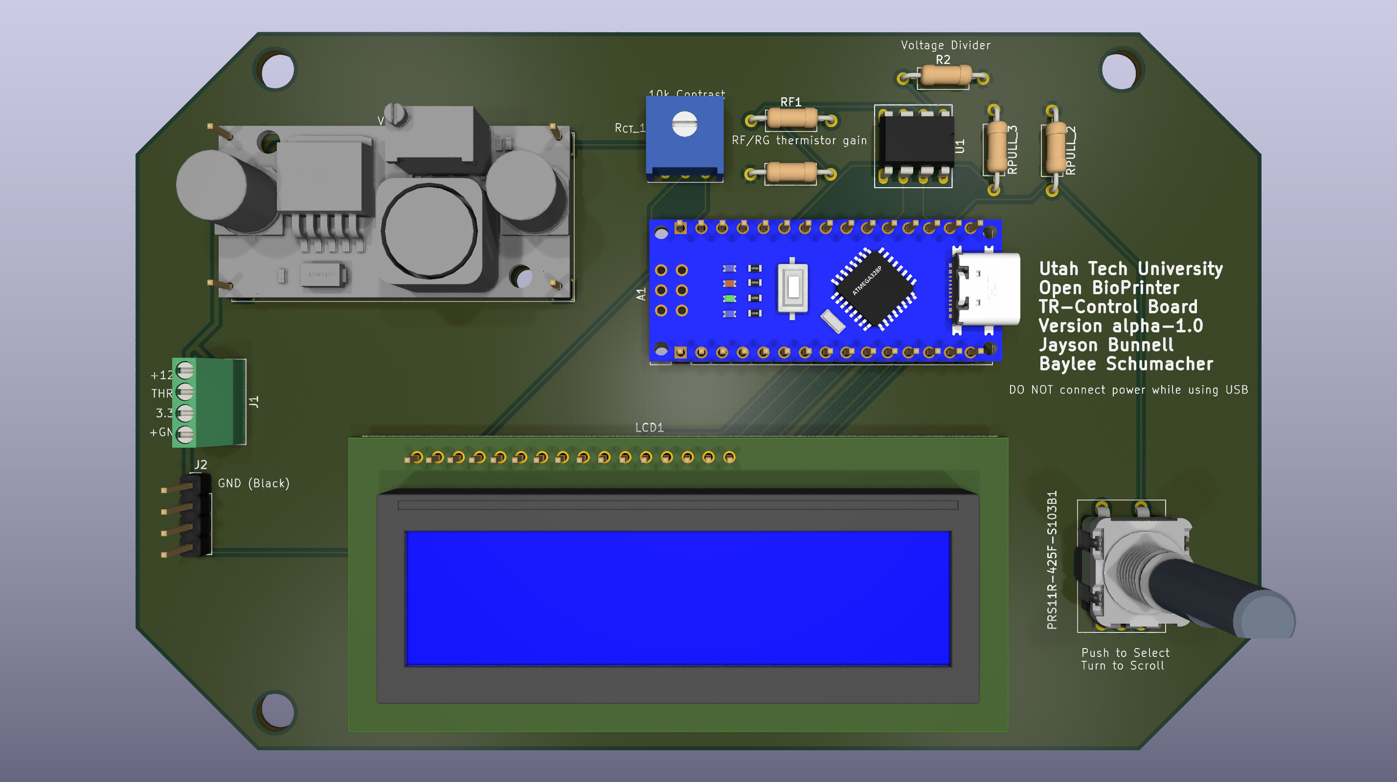
OpenBioPrint's Temperature Regulation Board.
A 3D render from KiCad 10 of the OpenBioPrint V-1 temperature regulation board. A second (better!) version of this board has been designed, but not manufactured.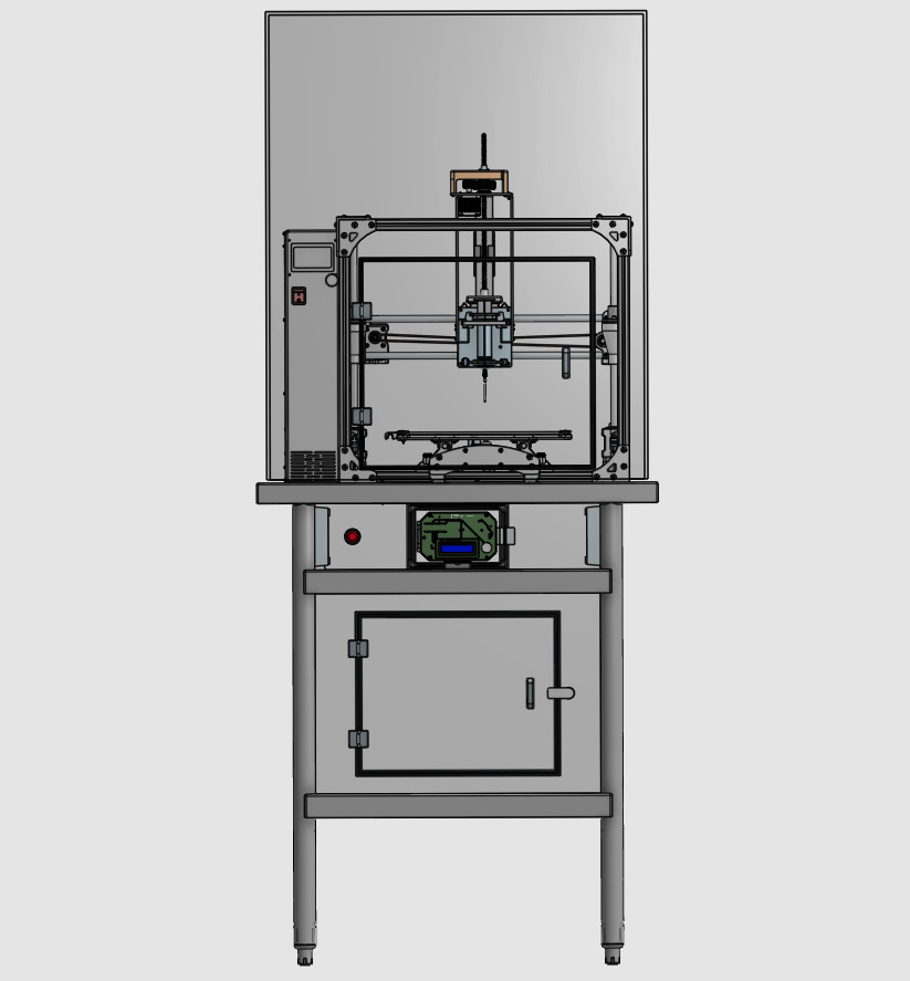
A Render of OpenBioPrint in OnShape.
A 3D render of OpenBioPrint in Onshape, modeled down to the last fastener. There are three separate enclosures; the upper, containing the modified TAZ6, the center, containing the E-STOP and temperature regulation control board, and the lower incubator compartment to act as a temperature controlled incubator.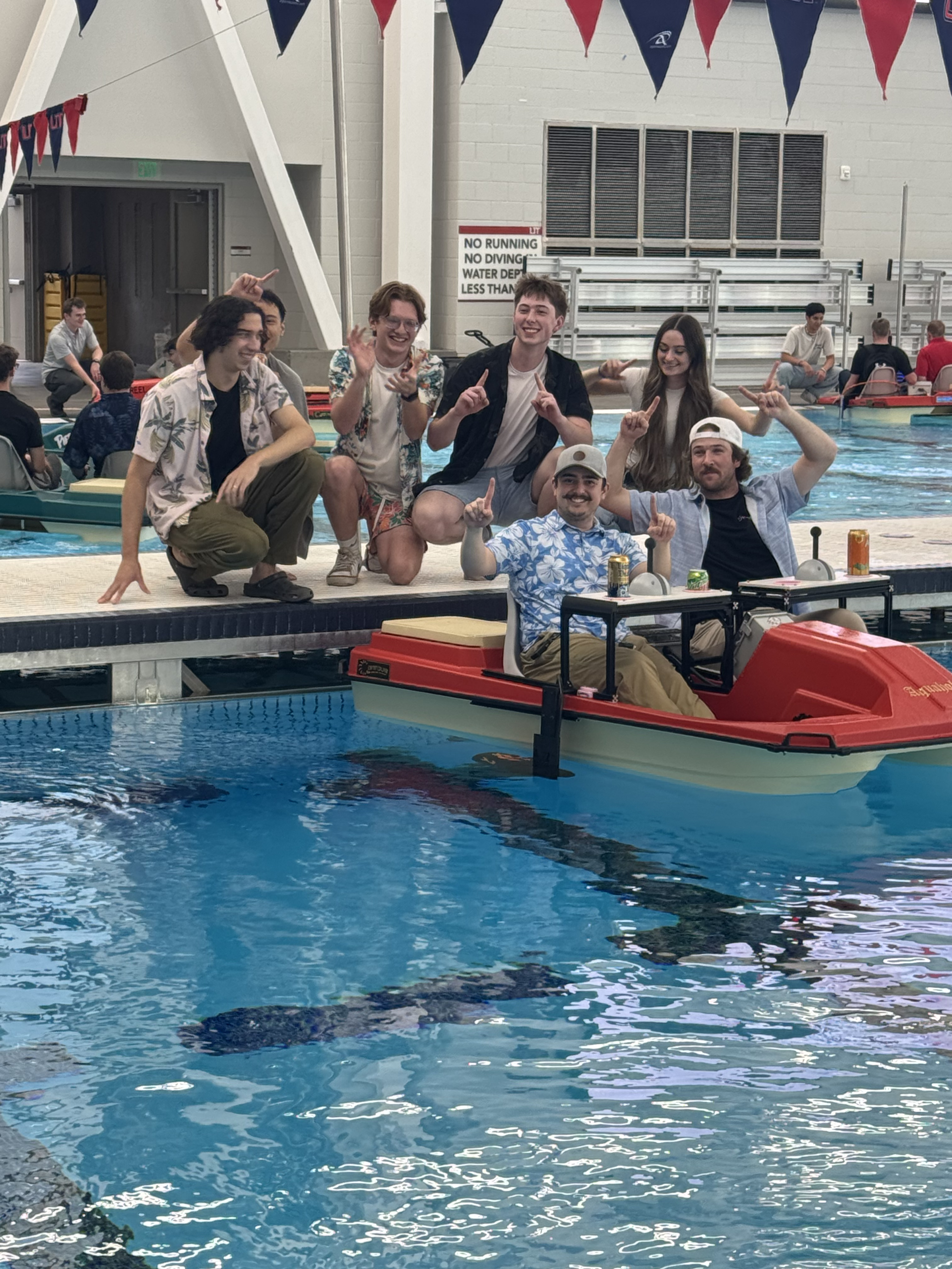
The Aquaholics team, posing before competition.
A photo of the aquaholics team. From left-to-right: Myself (yes, my hair was quite long!), Cody Cuenco (Obscured), Braydon Phillips, Blake Ehlers, Jacob Galindo, Joslyn Francis, and Mason Olson. You'll see the dual controls of our boat piloted by mock-lego joysticks. Sensor feedback and motor data are available on the screen in the center, and the power distribution system is in the cooler box on the back. This boat won first place in maneuverability and drag-race time.